Inserting a 3D Model into a Real Location: the Geometric Route Instead of a Screenshot and a Prompt
A design is rarely judged on its own. What gets judged is how it sits in what is already there: the neighbouring buildings, the eaves heights along the street, the existing trees, the terrain. That makes the question of how to insert a 3D model into a real environment a question about how much the image can actually tell you, not a question of aesthetics.
Two fundamentally different routes have established themselves for this task. One works with two images and a prompt, leaving the compositing to the AI. The other places the model geometrically at the real site before any image exists at all. This article describes both and walks through the second one step by step.
Disclosure: This article comes from the team behind VisioPlan and describes our own product among others – we are of course not neutral here. We describe the screenshot route from the vendors' own public instructions, not from our own testing, and we say where every limitation comes from. Research as of: 27 August 2026.
Why site context decides the presentation
A rendering against a white background answers the question of what the building looks like. It does not answer the question actually asked in a design review panel, at a public consultation or by an investor: how does this building work in this spot, between these houses, on this street?
That question cannot be answered with quality instead. A technically brilliant image without context remains an assertion. A simple image in which the viewer recognises the neighbouring buildings is an answer. Everything that depends on site context – shadowing of the adjacent plot, sight lines, height development against the existing fabric – only becomes checkable once the surroundings are right.
The common route: two screenshots and a prompt
The most thoroughly documented approach at the moment comes from the prompt-based platforms. Rendair AI describes it in five steps, and the guide is remarkably open about what it asks of the user:
- Open your 3D model and position the camera so that angle and perspective come as close as possible to the site photo – the guide explicitly recommends approximating the horizon and camera height.
- Obtain a site image: a photo taken on location, or a screenshot from a map service.
- Upload both images to the platform's chat.
- Select an image model and send the prompt – in the guide's own example: insert the house from the second image into the first, matching lighting, shadows and realism.
- Regenerate the result until the desired realism is reached.
The approach has real strengths, and they deserve naming: it needs no model integration, no IFC and no data pipeline. It works at any site for which a photo exists – including places with no 3D map data at all. And according to the vendor it works even with a model that is not finished. For a single image from a handful of inputs, that is a short route.
Where this route sits alongside the other AI rendering tools is covered in our comparison of ten AI rendering tools, pricing included.
Where that route breaks: perspective, scale, reproducibility
The decisive point is step 1, and it is there in the wording of the guide itself: the perspective is matched up front, by eye, by the user. That moves the hardest part of the whole exercise to the very beginning, into a step that gives no feedback. Whether focal length, eye level and tilt actually match the site image only becomes visible in the finished composite.
Three consequences follow, however good the image model is:
- Scale is estimated, not derived. Nothing in the image fixes the height of the design relative to the neighbouring building. Whether the new build sits two metres too high cannot be read off the composite – and that is exactly the figure a planning decision turns on.
- The second view is a new task. Every additional perspective needs a new site image, a new model view and a new attempt. A series of four consistent views of the same design does not come from moving the camera; it comes from repeating the entire process four times.
- Reproducibility is not part of the design. "Regenerate until it fits" is the instruction itself, not our sharpening of it. If the client wants to see the building shifted by two metres, there is no parameter for that.
None of this is a criticism of image quality, which is high with the current models. It is a statement about what ends up in the planner's hands and what does not. How prompt-based methods work technically, and where their limits of control lie, is set out in our guide to AI architectural rendering. That the same pattern is not limited to site placement, but already shows up in the simplest prompt-based rendering, is what our test in Why Prompt Engineering Is the Wrong Approach for Architects demonstrates.
The geometric route: from address to rendering
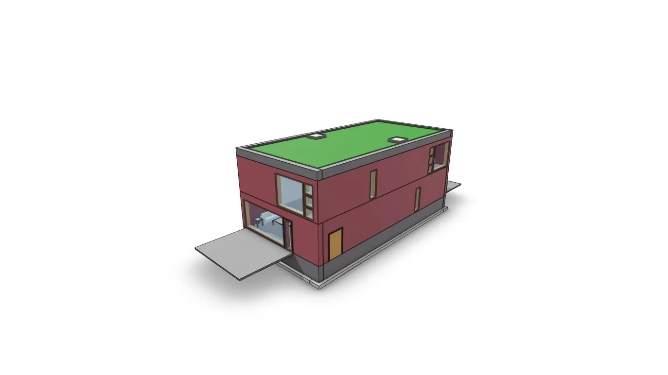
The second approach reverses the order. It does not insert the model into an image but into a three-dimensional environment, and produces the image only afterwards. The starting point is the model as it comes out of the CAD program.
Step 1: Enter the address
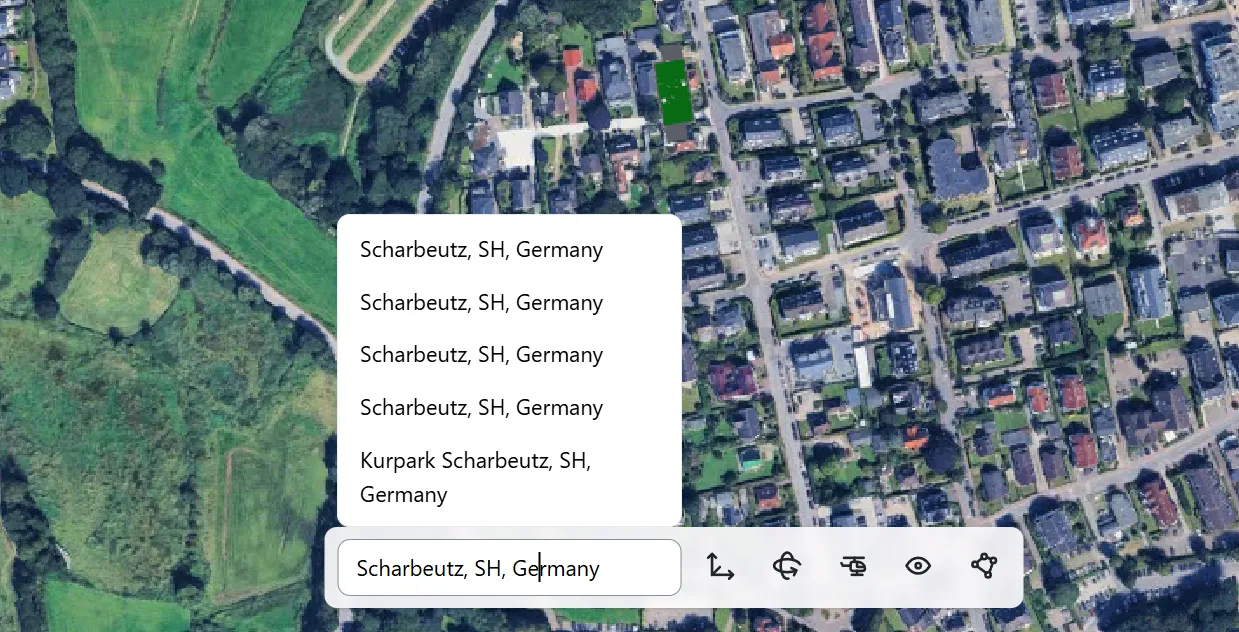
The site is not photographed but addressed. Entering the address loads the three-dimensional environment of the location – buildings, vegetation, streetscape, terrain.
Step 2: Place and align the model
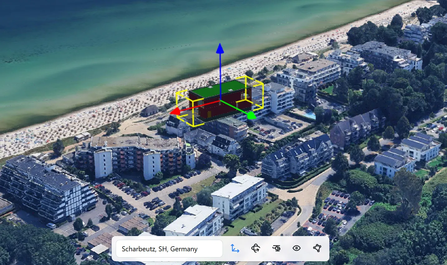
The model is placed on the plot and moved, rotated and adjusted in height along every axis using three-dimensional transform handles – against the actual neighbouring buildings, not against a photo of them. The hero image above shows exactly this state: model in context, axes visible, position still changeable.
The difference from the first route is fundamental at this point: the perspective does not have to be guessed in advance, because it is chosen freely after placement. You navigate the space and then decide what the image should show.
Step 3: Clip colliding context
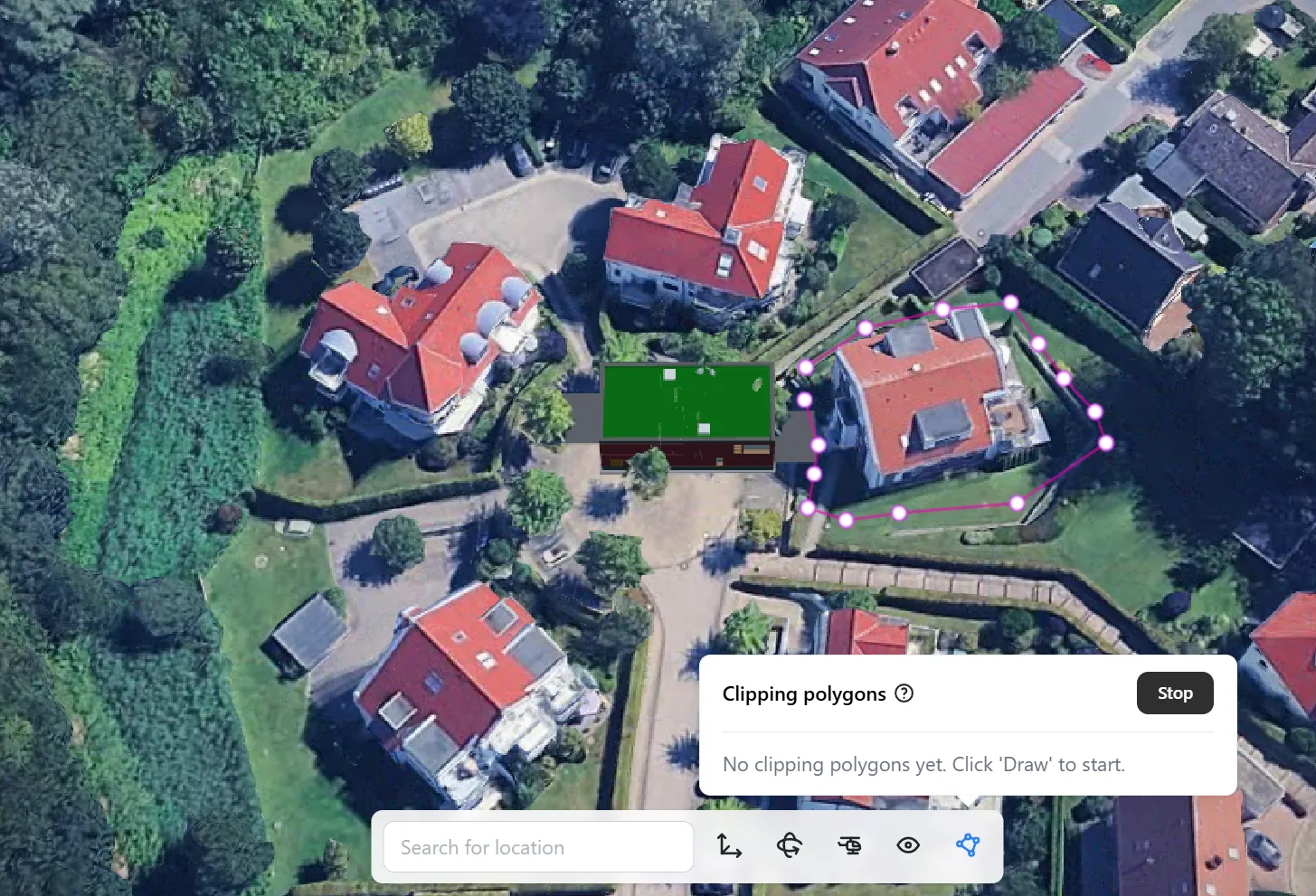
3D map data shows the location as it was flown. If an old building still stands on the plot, or a tree cuts into the new volume, the conflicting map geometry is removed from that area with a clipping polygon.
Step 4: Set the base image
The base image is captured from the chosen camera position. It already contains everything that is geometrically fixed: position, orientation, height, relationship to the existing fabric.
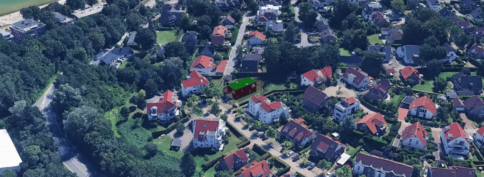
Step 5: Render
Image generation builds on that base image. Image style, time of day, season and weather are selected, not guessed at through a text description.
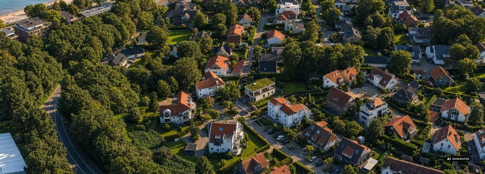
Because the geometry is fixed before the image, the camera is the only free parameter. A second view means moving the camera and rendering again. The site relationship survives that without having to be established a second time.
A second example: the same route on a new-build plot
The Baltic coast town above is the easy case: dense fabric, clear edges, plenty of context. The second run shows the same procedure on a new-build plot at the edge of a village – excavations, unfinished roads, adjoining fields.
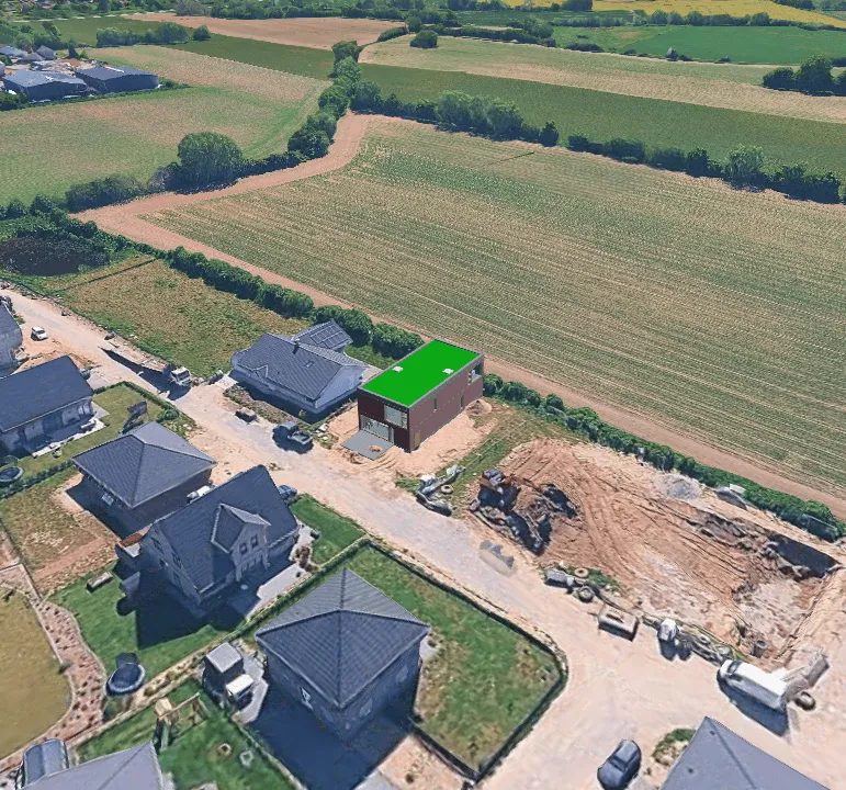
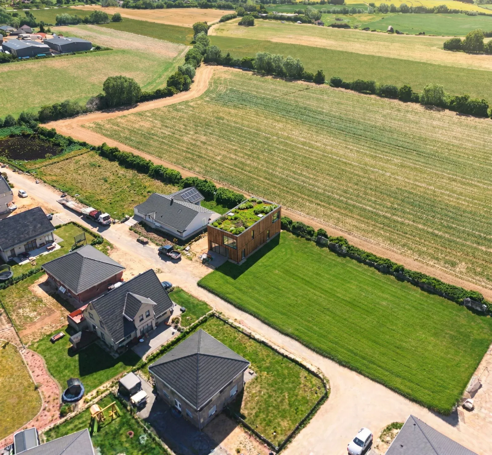
What matters here is less the building than the surroundings. The unfinished ground, the access road and the plot boundaries appear in the rendering where they were in the base image. That is precisely where a site photo used as an image source cannot keep up: whatever is geometrically defined stays where it is.
Where this route has limits too
Three constraints that come with the method and are worth knowing before choosing a tool:
3D coverage is not global. The contextual data comes from Google's photorealistic 3D data. Google states coverage as "2,500 cities across 50 countries" (Google Maps Platform, retrieved 27 August 2026); the developer documentation gives 49 countries elsewhere. More decisive than the number is the distinction in Google's own coverage documentation: 3D terrain data is available worldwide, 3D surface data – buildings and trees – only in the areas marked there. For a rural plot that can mean topography yes, neighbouring buildings no.
The data shows the state at the time of the flyover. Photogrammetry is a snapshot. A neighbouring building completed last quarter may be missing. For the plot itself the clipping polygon solves this; for the surroundings it does not.
It needs a model. The route presupposes geometry. With us, CAD model import is a feature of the Pro tier, not of the entry tier – if all you have is a sketch, the first route serves you better. And neither route is intended for checking boundary distances: the method is for urban-scale and atmospheric presentation, not for surveying.
How the feature came about and what it does in detail is in the product piece on the Google Viewer.
Which route is right when
| Criterion | Screenshot and prompt | Geometric site anchoring |
|---|---|---|
| What you bring | Site image and model view, perspectives matched by eye | A 3D model and an address |
| Who fixes the perspective | You, up front, in CAD and when shooting | You, in the viewer, after placement |
| Site geometry | read off the image | from 3D geodata, navigable in space |
| Second view of the same design | new image, new model view, new attempt | move the camera, render again |
| Shifting the position by two metres | another full run | move the model, render again |
| Sites without 3D coverage | works | does not work |
| No finished model yet | works, per the vendor | does not work |
The screenshot route is the right choice when one of these applies: the site has no 3D surface data; the plot has changed since the flyover; there is no model yet, only a sketch; or you have a particular photo from the site and that specific view is the one you want.
The geometric route is the right choice as soon as more than one image is needed, as soon as height development against the existing fabric is part of the argument, or as soon as somebody is likely to ask for a change.
Frequently asked questions about inserting 3D models into real environments
What files do I need to place my model in its real surroundings?
A 3D model and an address. The model reaches the browser as an IFC file or through a live connection to the authoring system; alternatively, 2D images and sketches can be uploaded. CAD model import is part of our Pro tier.
Where does the three-dimensional environment come from?
From Google's photorealistic 3D data. Terrain data is available worldwide, surface data such as buildings and trees only in the areas Google marks – stated as roughly 2,500 cities in around 50 countries as of 27 August 2026.
What happens to trees or existing buildings that cut into the design?
They are removed from that area with a clipping polygon. The planner traces the outline and the conflicting map geometry is hidden there.
Can I produce several views of the same design?
Yes, and that is the main practical difference. Because the model is geometrically located, the camera is the only free parameter: move it and render again. The site relationship does not have to be re-established.
Is this suitable for checking boundary distances?
No. The method is for urban-scale and atmospheric presentation. For setback areas, boundary distances and height limits, the site plan remains the basis.
Conclusion
Both routes produce an image of the design in its real location, and both have their use case. The difference is not image quality but when the perspective gets decided. On the screenshot route it is decided up front, by eye, without feedback – and every change means another full run. On the geometric route the position is fixed before the first image exists, and the camera stays free.
If you need one image, either will do. If you need a series, or expect somebody to ask about the height, locate the site rather than depict it.